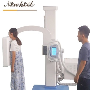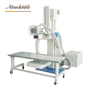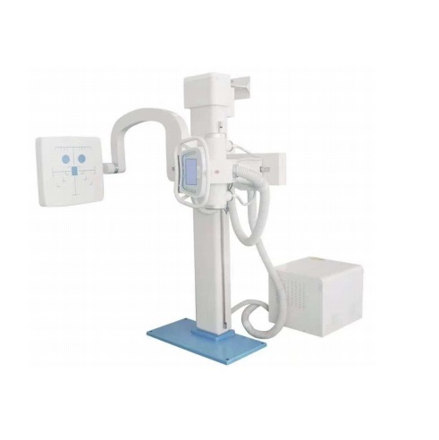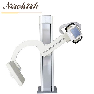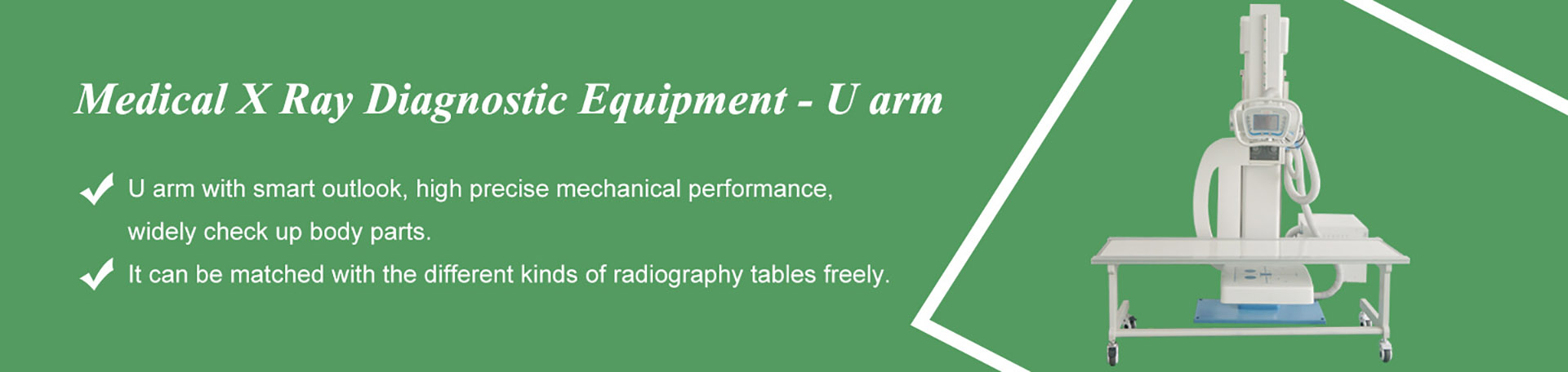

Quick answer: a vehicle-mounted X-ray system is a radiography room constructed inside a vehicle body, with the examination space, the operator position, the shielding, the generator, the stand and the acquisition workstation treated as one installed system. A portable unit placed in a van remains a portable unit. The distinction is not about where the equipment travels; it is about which parts of the examination environment are built into the vehicle and which parts are carried to a site. The vehicle-mounted digital radiography system and the dual-column rack family for examination vehicles are two separate product entries because the first describes the installed room and the second describes the mechanical stand fitted inside it.
Enquiries about vehicle-mounted equipment often arrive with one product name attached to several different things: a complete vehicle, a radiography system intended for installation in a vehicle, or a stand designed for the limited floor area of a vehicle compartment. These are not interchangeable line items, and a quotation built around the wrong one tends to leave out either the vehicle work or the imaging chain.
The installed-system reading is used here. Under that reading, the examination space is a defined volume with a patient position, a tube and stand assembly, a detector position, an operator workstation, and a separation between the two working zones. The vehicle body carries the shielding, the power distribution, the fixings for the equipment and the services that an ordinary radiography room would receive from the building. The equipment description therefore has a boundary at the vehicle structure, and the vehicle description has a boundary at the equipment interfaces.
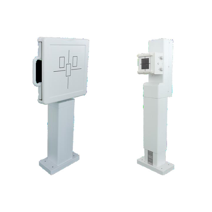
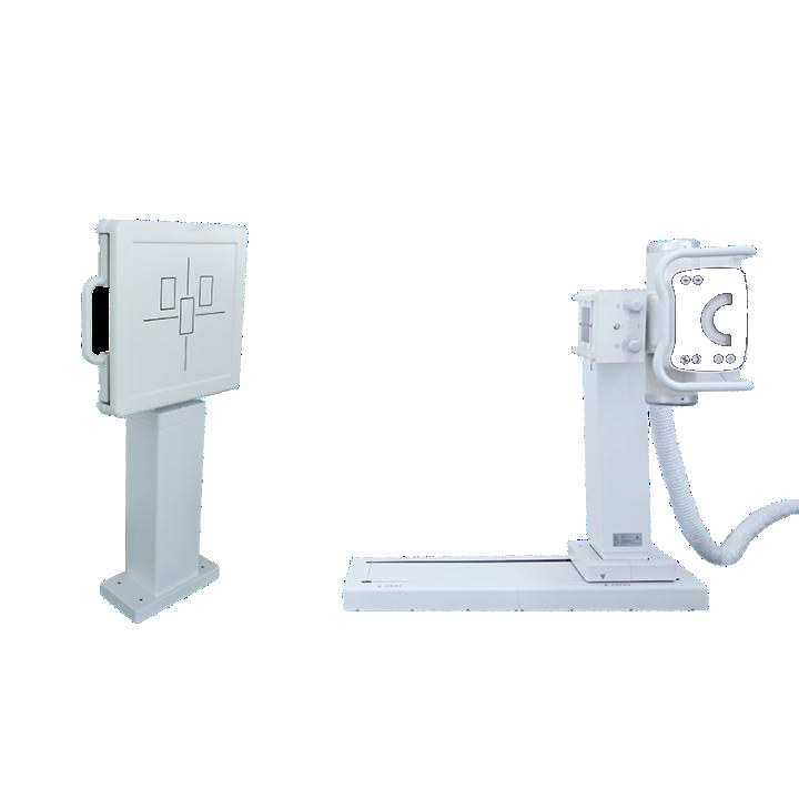
This is also why the stand has its own product entry. A dual-column rack family for examination vehicles addresses a compact footprint, electric vertical adjustment, and variants that accept a combined machine head, a tube with collimator, or a portable generator. Those are stand-level decisions. The room-level decisions — compartment layout, shielding continuity, supply arrangements, workstation placement and the documents that close out the installation — belong to the system description.
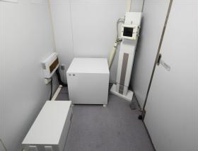
In a fixed department, the room exists before the equipment arrives. The walls, the supply, the controlled area and the operator position are building features, and the radiographic equipment is installed into them. In a vehicle-mounted system the same features are produced as part of the vehicle build. The examination zone and the operator zone are laid out together, the shielding is continuous across the panels that separate them and across the outer skin, and the stand is fixed to a structure designed to take its load in transit as well as during an exposure.
The practical consequence is that a change to the stand can require a change to the vehicle, and a change to the vehicle can require a change to the stand. A taller column, a different detector position or a relocated generator cabinet alters clearances, cable routes, shielding joints and the position of the operator workstation. These are interface decisions made before fabrication, not adjustments made on a handover day.
The compartment also carries the visible markers of a radiographic room: warning signage at the access point, a defined operator position, and a clear separation between the area where the exposure takes place and the area where the acquisition workstation sits. Those features are part of the installation, so they appear in the layout drawing and in the acceptance record rather than in a description of a portable machine.
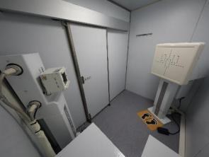
A portable generator is specified against the mains supply available where it is used. A vehicle-borne radiography system is specified against the supply that the vehicle can provide or receive at the places where it will be parked. The distinction sounds small and is not. The generator, the distribution cabinet, the cable entry, the protective earthing arrangement and the voltage stability at the moment of exposure are all settled as part of the installation design, because the vehicle is both the room and the point of connection.
Site conditions therefore become inputs to the specification rather than assumptions in a brochure. The operating organisation states where the vehicle will be stationed, which external supply is available at each stopping point, and whether a separate supply arrangement is part of the project. Those statements determine the distribution design, the earthing scheme and the written conditions under which an exposure may proceed. A system described without them is a collection of components, not a commissioned room.
The same applies to environmental conditions inside the compartment. Temperature, humidity, ventilation and condensation control affect the generator, the workstation and the detector, and they are handled by the vehicle builder together with the equipment supplier. The written specification records which party is responsible for each interface; the acceptance record confirms that each interface was tested.
A fixed room has one state. A vehicle-mounted room has at least two: parked and prepared for examinations, and closed for travel. The second state has its own requirements. Moving parts are brought to a transport position and secured, the detector and any removable assemblies are placed in dedicated stowage, doors and cabinets are latched, and the operator workstation is protected against vibration. A stand intended for vehicle use is designed with that state in mind, which is one reason a general-purpose upright stand is not automatically a vehicle stand.
On arrival, the return to the examination state is a procedure, not a single switch. The transport restraints are released, the stand is returned to a defined reference position, the geometry is confirmed, and the imaging chain is checked before the first examination of the session. The checks belong in the operating documentation supplied with the installation, because a repeat examination caused by a disturbed geometry is a workflow loss rather than a detector problem.
Transport also changes what counts as maintenance. Fixings, restraints, cable clamps and stowage points are inspected with the same regularity as the imaging components, since a loose fixing discovered during a session has consequences beyond the image. The inspection list is part of the handover documentation and is referenced in the service arrangement.
The purpose of building a radiography room into a vehicle is to take an examination service to a population that is not attending a fixed department: outreach screening, occupational health programmes, remote sites and emergency response. The registration, the radiation protection arrangements and the operating procedures follow that purpose. A vehicle-mounted system is not normally treated as the routine diagnostic equipment of a fixed department, and a programme that needs permanent, high-throughput room coverage is usually specified as a fixed installation instead.
That boundary has a documentary form. The intended use is stated in the project documents, the operating organisation retains responsibility for radiation protection, and the applicable requirements are those of the regulator in the country of use. Where a temporary controlled area is established around a parked vehicle, its extent, the warning arrangements and the exclusion of uninvolved persons are set out in the local procedure and confirmed by the acceptance measurements. No equipment description substitutes for those documents.
It also has a commercial form. A quotation for a vehicle-mounted system that omits the vehicle work, the shielding, the supply arrangement or the acceptance documentation is a quotation for part of a system. Enquiry correspondence that separates these line items early tends to produce a specification that can actually be built and signed off.
The four arrangements below are frequently grouped under the word “mobile”. Their differences are structural rather than a matter of size or power, which is why a comparison based on generator ratings alone gives a misleading answer.
| Configuration | Where the room is | Supply and site | Transport state | Use boundary |
|---|---|---|---|---|
| Fixed radiography room | A prepared department with building-provided walls and services | Building supply and earthing designed for the installation | Not applicable | Routine diagnostic work at one location |
| Vehicle-mounted system | An examination compartment built into the vehicle body | Vehicle distribution plus the external supply stated for each stopping point | Defined restraint, stowage and recommissioning procedure | Outreach, screening and emergency service across locations |
| Mobile ward unit | Wherever the unit is pushed; the room is the ward or corridor | Local mains or an on-board battery arrangement | Parked and moved between beds, with cable and accessory stowage | Bedside examinations for patients who cannot be moved |
| Portable unit in a carrying case | Wherever the unit is set up; the surroundings are not prepared | Available mains or battery, assessed at each site | Packed into cases between sites | Field, veterinary and occasional examinations |
The bedside workflow description covers the third row, and the overview of devices sold under the handheld name covers the naming problem behind the fourth. This article stays with the second row.
Interface ownership is the part most often missing from an enquiry. A vehicle builder needs to know the position, mass, fixing pattern, cable routes and service clearances of each equipment item. An equipment supplier needs to know the internal dimensions of the compartment, the position of doors and access panels, the shielding construction and the arrangement of the operator zone. Neither side can close its design until the other side has committed to numbers in a drawing.
The clean way to handle this is an interface schedule attached to the specification. Each row names an item, the party that supplies it, the party that installs it, the drawing that fixes its position, and the document that confirms it at acceptance. Shielding continuity, earthing, cable penetrations, the stand base and the workstation are typical rows. Where a row has no owner, it tends to surface later as a delay rather than as a design question.
The table below lists the inputs that belong in writing before a vehicle-mounted system is priced or fabricated. None of them is a performance claim; each is a condition that determines the configuration.
| Input | What the written statement has to cover | What it fixes |
|---|---|---|
| Vehicle and compartment | Measured internal dimensions, door and access positions, and the intended division of the two working zones | Stand form, patient positioning clearances and workstation location |
| Examination programme | The projections and examinations the service is planned to perform | Stand geometry, detector position and accessory list |
| Supply and earthing | The external supply at each stopping point, the distribution arrangement and the protective earthing scheme | Generator and distribution design, cable entry and exposure conditions |
| Radiation protection | The shielding construction of the compartment, the signage and the arrangement of the temporary controlled area | Vehicle bodywork, access positions and the local operating procedure |
| Image and data handling | Acquisition workstation placement, image storage, transfer and archive route, and the information system interface | Workstation specification and network provisions inside the vehicle |
| Regulatory scope | Country of use, the responsible registrant, and the documents required for registration and acceptance | The acceptance test plan and the handover documentation set |
Values for these inputs come from the measured vehicle, the programme description and the applicable regulations, in that order. A specification that fills the gaps with assumed values gives a plausible-looking document that cannot be built without change.
A vehicle-mounted installation is accepted as a system. The record set therefore has to show that the room, the equipment and the vehicle work together, not merely that each item was delivered.
| Document | What it settles | When it is issued |
|---|---|---|
| Signed specification and interface schedule | Configuration, responsibilities and the drawing revision that governs the build | Before fabrication |
| Layout and shielding drawings | Compartment zones, panel construction, penetrations and fixing positions | With the build documentation |
| Installation and commissioning record | Stand alignment, geometry, supply checks, earthing and workstation integration | At commissioning |
| Radiation protection survey report | Measured conditions around the parked vehicle and the resulting controlled area | Before first use |
| Operating and transport procedure | Preparation for travel, recommissioning on arrival, daily checks and exclusion arrangements | At handover |
| Training and service records | Named responsibilities, maintenance intervals and the route for reporting defects | At handover and during service |
The acceptance conclusion rests on those documents and on the applicable regulations in the country of use. A product label, a catalogue description or a component data sheet does not establish it.
This article stops at the system boundary. Detector construction, scintillator and backplane technology, pixel-level performance and DICOM integration belong to the detector-focused site, and are not restated here. Likewise, rack structure, load ratings and mechanical travel figures belong to the site that covers stands and U-arm structures; the vehicle stand entry and the detector-focused site are the respective references. Keeping those layers separate prevents a specification from accumulating figures that no single party has confirmed.
Three patterns recur in enquiries and in published material, and each one produces a quotation that is difficult to build against.
The first is a portable machine described as a vehicle system because a van appears in the photographs. The presence of a vehicle does not create a built-in examination room; the room-level items — shielding, distribution, fixings, zones and acceptance documents — are still missing from that description.
The second is a stand described as a complete system. A stand is a real and necessary line item inside a vehicle build, and its variants matter, but a stand specification does not cover the generator, the workstation, the compartment or the regulatory file.
The third is a vehicle system offered as a permanent department replacement. The intended-use statement, the registration basis and the radiation protection arrangements differ, and a programme built on that substitution tends to be re-specified after the documents are reviewed.
In each case the correction is the same: return to the written inputs, name the owner of each interface, and restate which documents close out the installation. That is the difference between an equipment list and a room that can be put into service.
It is not. A vehicle-mounted system has the examination zone, shielding, distribution, fixings and workstation built into the vehicle structure and accepted together as one installation. A portable unit remains a separate device that is carried to a site and set up against the conditions found there.
The intended use of a vehicle-mounted system is outreach, screening and emergency service across locations. A permanent department with routine diagnostic throughput is normally specified as a fixed installation. The applicable scope is stated in the registration and project documents, with radiation protection requirements set by the regulator in the country of use.
The external supply available at each stopping point, the vehicle distribution arrangement, the protective earthing scheme and the voltage stability under exposure are settled in the specification. They determine the cable entry, the distribution cabinet and the written conditions under which an examination may proceed.
A signed specification with an interface schedule, layout and shielding drawings, an installation and commissioning record, a radiation protection survey report, the operating and transport procedure, and the training and service records. Together these establish that the room, the equipment and the vehicle work as one system.
Detector technology and image-chain parameters are covered on the detector-focused site. Rack structure, load ratings and mechanical travel figures are covered on the stand and U-arm site. A system specification references those documents rather than restating figures that have not been confirmed by the responsible party.
Specification sheets, configuration options and scope confirmation for vehicle-mounted radiography systems are available on request. Written correspondence is handled at admin@newheek.cn. Telephone and WhatsApp contact: +86 19062611512 (WhatsApp). An enquiry page is provided for structured requests.
Tel: +86 19062611512
Email : admin@newheek.cn
Company : Weifang Newheek Electronic Technology Co., Ltd.