
Quick answer: an industrial X-ray inspection is complete only when an independent reviewer can reproduce the geometry, confirm the image quality that was achieved, and trace the radiograph back to one identified part. The exposure itself produces an image. The examination produces a file: written inputs, a documented setup, an image quality check, an interpretation, and an archived original that can be read again months later. The equipment that performs the examination is described in the overview of X-ray NDT equipment and system types; this article follows what has to be recorded around one examination.
Phone / WhatsApp: +86 19062611512
Email: admin@newheek.cn
Medical radiography ends at a diagnostic image read by a clinician. Industrial radiography ends at a record that a second party can audit. A weld on a pressure component, an electrical insulation casting, or a bonded assembly may be inspected again years after manufacture, by a different organisation, under a contract that no longer has the original operator available. The radiograph carries meaning only if the conditions that produced it travel with the image.
That difference shapes every step below. It is also why two documents that sound similar are kept apart in practice: the radiographic technique standard describes how an image of adequate quality is produced, while an acceptance standard describes which indications are permissible in the finished part. ISO 17636-1 (film techniques) and ISO 17636-2 (computed radiography and digital detector arrays) belong to the first group; ISO 10675 belongs to the second. Conflating the two produces files that are technically neat and contractually useless.
A job card arrives with the part: an identifier, a material or material group, a section thickness range, a zone or weld reference, and the extent of coverage required. On a fabrication floor the identifier is often a paint mark or a taped tag that does not appear in the radiograph. Lead characters or radio-opaque location markers placed beside the zone during exposure solve that problem: the image then contains its own reference to the object, and a later reviewer can match a shadow to a position on a drawing.
Intake also fixes what is not being examined. A file that records coverage as “the whole assembly” gives an auditor no way to tell whether a given region was in the field of view. A file that names the zones and their markers does. Where several parts share a setup, each part keeps its own identifier in the record even when one exposure covers a batch.
Nothing in an examination should depend on a verbal understanding. The governing documents are named on the technique sheet before the source is energised: the edition of the technique standard, the image quality class required by the contract, the acceptance document used at interpretation, the IQI family and material group, and any customer specification that overrides a general practice. Mixing an ISO wire IQI selection table with an ASTM hole-type requirement is a common source of disputes, because the two systems do not share the same designation logic.
| Input | What it fixes | Where it is captured |
|---|---|---|
| Part identity and zone markers | Which object and which region the image belongs to | Job card and marker layout on the radiograph |
| Technique standard and edition | The minimum radiographic practice for the job | Technique sheet |
| Required image quality class | The IQI sensitivity the exposure has to demonstrate | Contract reference on the technique sheet |
| Acceptance document | The criteria used later at interpretation | Inspection plan or contract |
| IQI family and material group | Which indicator is placed, and which reading applies | Technique sheet and exposure record |
| Capture medium | Film, computed radiography plate, or digital detector array | Technique sheet and image metadata |
The edition matters as much as the number. A contract may cite an older edition of a standard that a supplier has since replaced internally; the contract edition governs unless the parties agree otherwise in writing. Standard numbers are written without version years on this page for exactly that reason.
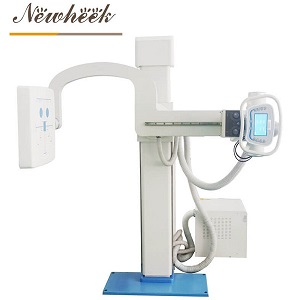
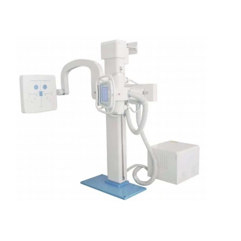
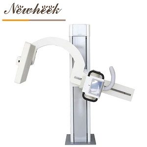
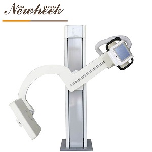
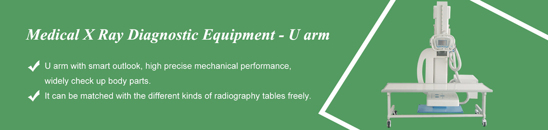
Three positions define a radiographic setup: the source focal spot, the test object, and the imaging plane. Source-to-detector distance, the angle of the beam to the region of interest, and the offset between the part and the capture plane determine geometric unsharpness and the apparent shape of an indication. A column, stand or fixture holds those positions still. On repeat inspections of the same component, the fixture also makes one exposure comparable with the next, which is why the same hardware appears in both medical radiography rooms and industrial inspection cells.
The image quality indicator is placed at this step, not added afterwards. Wire-type indicators (ISO 19232-1, ASTM E747), step/hole-type indicators (ISO 19232-2, ASTM E1025) and duplex wire indicators (ISO 19232-5) are radiographed together with the part. Placement on the source side or the detector side is recorded, as is the material group of the indicator, which is chosen to match the absorption of the part rather than the convenience of the kit on the shelf.
A small detail with large consequences: the indicator has to sit in the region whose image quality is being claimed. An IQI parked on a thin edge of a stepped casting says nothing about the thick section at the centre of the same exposure.

The technique sheet is the bridge between the setup and the image. It records the source settings used, the geometry, the capture medium and its identifier, the IQI position, the processing route for film or the acquisition settings for a digital system, and the operator and date. On film-based work the processing chemistry and conditions belong here, because a well-exposed radiograph can be degraded afterwards. On digital work the acquisition software, calibration state and export format belong here, because a grey value image separated from its metadata loses the evidence that it was acquired under controlled conditions.
Detector-side parameters – pixel pitch, scintillator, active area, frame rate – are a separate engineering subject, documented on the industrial NDT flat panel detector page on the detector-focused site. The examination record needs the identifier and state of the panel that was used, not a restatement of its design.
ISO 17636-2 states the intent of the digital route plainly: the minimum radiographic practice is set so that digital acquisition can reach sensitivity equivalent to film radiography under ISO 17636-1. The record has to show that this was achieved on the day, for that part, rather than assumed from the equipment catalogue.
Before any indication is interpreted, the image itself is checked. For film, optical density and viewing conditions (ISO 5580) are verified; for digital images, grey value range, display conditions and basic spatial resolution are verified. The smallest visible wire, or the required hole in a step/hole indicator, is read and written down. A duplex wire reading is used where total image unsharpness has to be demonstrated for a digital technique.
| IQI family | Standard family | What the reading demonstrates | What it does not demonstrate |
|---|---|---|---|
| Wire type | ISO 19232-1; ASTM E747 | The thinnest wire visible under the actual exposure, geometry and viewing conditions | That every defect type in the part is detectable |
| Step / hole type | ISO 19232-2; ASTM E1025 | Contrast and detail sensitivity through the required hole and step | Conformity of an indication to an acceptance level |
| Duplex wire | ISO 19232-5 | Total image unsharpness and basic spatial resolution, mainly for digital techniques | The absence of handling or processing artefacts |
The distinction in the last column is worth keeping in view. An IQI is a calibrated control device, not a flaw simulator. A clean reading says the technique reached its required sensitivity; it says nothing about whether a particular lack-of-fusion plane was oriented favourably to the beam. Interpretation is a separate step with separate criteria.
Interpretation applies the acceptance document to the indications visible in a radiograph of verified quality. Two outcomes are often confused at this point: a rejected image and a rejected part are different findings. A rejected image is a documentation or quality failure – insufficient sensitivity, missing markers, an incomplete technique sheet, unsuitable viewing conditions – and leads to a repeat exposure. A rejected part is a decision about indications under the acceptance criteria.
The repeat exposure is itself a record. An entry reading “retake” tells an auditor nothing; an entry naming the failed check, the corrected setup, and the disposition of the first image keeps the file reviewable. Keeping both images, with the first one clearly marked as superseded, is more defensible than deleting it: a reviewer can then see what changed and why.
The archive is where a record trail proves its worth. A film radiograph is stored with its identification strip, technique sheet and interpretation report, protected from handling damage. A digital examination is stored as the original acquisition file with its metadata intact, in a read-only location, with the viewing and reporting conditions recorded alongside. Exporting a convenient copy for email is normal practice; treating that copy as the record is not.
Retrieval keys matter more than folder names. Part identifier, zone or weld reference, examination date, technique sheet number and disposition let a reviewer find one examination among thousands. Retention periods come from the contract and the applicable regulatory framework, not from a storage policy invented at the workstation. A file that can be found, read and reproduced is the deliverable; an image without those links is a picture.
| Record | Question it answers | Consequence when missing |
|---|---|---|
| Part identification and zone markers | Which object and region does the image show | The radiograph cannot be tied to a location on the part |
| Governing documents and edition | Which practice and acceptance criteria applied | Results cannot be assessed against the contract |
| Technique sheet | How the exposure was set up and captured | The examination cannot be reproduced |
| Geometry and IQI placement | Whether the claimed sensitivity covers the region of interest | Image quality readings lose their meaning |
| IQI reading and viewing conditions | Was the required image quality achieved on the day | Interpretation rests on an unverified image |
| Interpretation and disposition | What was found and what was decided | No traceable outcome exists for the part |
| Re-exposure log and archived original | What changed between attempts, and what the source image was | Repeat work looks like an unexplained discrepancy |
Reviews of examination files tend to find the same small failures. Marker strips are photographically clear but placed outside the coverage zone. An IQI is present, yet the material group in the technique sheet belongs to a different alloy family. The exposure settings are recorded as a software default rather than the values used for that shot. A digital image has been exported to a common format and separated from its acquisition metadata. A repeat exposure sits in the same folder as the first, with identical identifiers and no note explaining which one was accepted.
None of these failures involves the X-ray source. Each one involves a document that seemed unnecessary at the moment the exposure was made. The pattern is consistent enough that a short pre-exposure checklist, read against the technique sheet at the workstation, prevents more rework than any upgrade to the imaging chain.
A catalogue label is not a capability statement. Equipment described as an industrial X-ray machine is qualified by its rated specification – tube voltage range, focal spot, duty cycle, and the inspection scope stated in its documentation – and by the standard under which a given examination is performed. A name that includes the word industrial does not establish suitability for a particular material, thickness or code requirement; the written specification and the governing procedure do.
The published scope of the industrial X-ray machine covers non-destructive examination of electrical insulation components: APG parts, switch pillars for high-voltage gear, and assembled insulation sets. A second product entry presents the digital capture variant. Suitability for a specific examination is confirmed against the written specification and the contract documents before planning begins.
An image quality indicator demonstrates the sensitivity achieved by a specific exposure, geometry, capture medium and viewing condition. The reading is a control result for the technique. It does not prove that every defect orientation or defect type in the part would be detected, and it is not an acceptance criterion for indications.
ISO 17636-2 sets minimum radiographic practice for computed radiography and digital detector arrays with the aim of sensitivity equivalent to film techniques under ISO 17636-1. The governing contract names the standard and edition that apply. Detector design parameters are a separate topic covered on the detector-focused site.
The technique standard addresses how an image of adequate quality is produced. Acceptance levels for indications are set in separate documents, such as the ISO 10675 series, or in a customer specification. An examination file records both, because a technically good radiograph can still show indications that fail the acceptance criteria.
A repeat exposure follows a failure of the image or its records: insufficient demonstrated sensitivity, missing or misplaced identification, an incomplete technique sheet, unsuitable viewing conditions, or processing and export problems that compromise the image. The reason, the corrected setup and the disposition of the first image are entered in the file.
Suitability is established from the published specification and the governing procedure, not from a product label. Material, section thickness, required image quality class and the applicable acceptance document all have to be matched to the rated capability of the equipment and confirmed in writing before an examination is planned.
Industrial X-ray equipment specifications, digital configuration options and examination-scope confirmation are available on request.
Phone / WhatsApp: +86 19062611512
Email: admin@newheek.cn
Enquiry form: contact page.
Tel: +86 19062611512
Email : admin@newheek.cn
Company : Weifang Newheek Electronic Technology Co., Ltd.